
The following article was written by Martin Albrecht (President, MT Propellers). Albrecht will be speaking at 3:30pm on Friday, April 14th about MT Propellers at King Air Gathering 2023.
With the improvement in materials and Computational Fluid Dynamics (CFD) software, the trend toward more blades on propellers is clear. From the original standard of 3-blade propellers, technological advancements have allowed for the development of 5-blade or even 7-blade propellers, which are increasingly common for turboprop applications.
Classic propellers were made with hubs from steel and utilized aluminum blades. Propellers with more than 3 blades, or even 5 blades, were not possible because of engine and airframe limitations due to the limiting factor of their weight.
With the availability of newer materials, the transition to propellers made with light-weight aluminum hubs combined with light-weight composite blades was made possible. Composite blades can now be made from a special high strength plasticized structural wood combined with carbon fiber layers or a foam core wrapped with carbon fiber.
These new materials allowed for 4, 5, or even 7-blade propeller systems with minimal increases in the overall weight. Additionally, with lighter weight blades, a reduction of gyroscopic moment lowers the loads on the engine/airframe by up to 40%.
A propeller produces thrust through a momentum transfer from the propeller to the air by the rotation of the propeller blades. Propellers are designed to produce maximum thrust from the torque (a function of HP and RPM) supplied from the engine.

The purpose of a propeller is to convert engine power, delivered by the rotating engine shaft, into thrust and to do so as efficiently as possible throughout the flight envelope. Propeller efficiency is therefore a function of the ratio of the power produced by the propeller to the engine power applied to it. The definition is as follows:
Thrust Power [W] = Thrust [N] * Velocity ( Distance [m] / Time [s] )
Torque Power [W] = Torque [Nm] * Rotational Speed [RPM] / 60 sec
Propeller Efficiency = Thrust Power [W] / Torque Power [W]
With the improvements in propeller system design over the years, efficiencies of 87% to 90% are possible in propeller systems produced today.
A propeller is designed just like an aircraft wing to create lift. The optimum lift for the highest efficiency occurs with a Coefficient of Lift (CL) between 0.4 and 0.7, ideally reduced to a minimum at the blade tip.
Propeller performance is characterized by thrust, propeller efficiency and power coefficient. The power coefficient is related to how much power is takes to turn the propeller and the propeller aerodynamic loading. Power Coefficient (CP) can be defined by the following equation:

where P is Power, ρ is the density of air, N is propeller RPM and D is propeller diameter.
As can be seen in the equation above, a change in the diameter of the propeller has 5 times more impact on aerodynamic loading than changing Power.
Modern simulation software (CFD) takes into account the aerodynamic flow, including compressibility losses on the blades at high Mach numbers. By shaping the blade with twist, providing an ideal angle of attack with oncoming air along the blade, and incorporating a scimitar shape, swept-back blades similar to airplane wings, the critical Mach numbers can be avoided, minimizing compressibility losses especially at higher altitudes (low air density) and higher speeds.
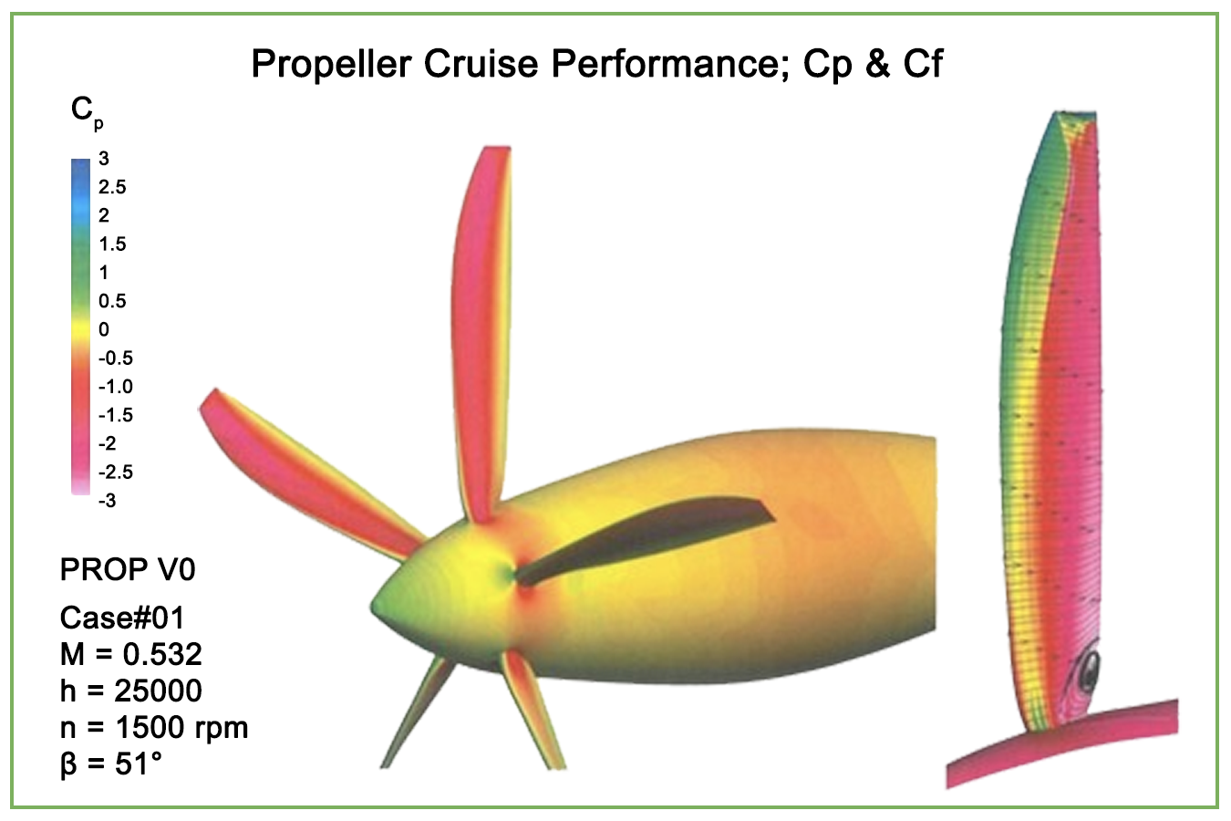 The very best contemporary propellers can approach 90% peak conversion efficiency, but with any propeller, the efficiency drops very rapidly as the tip velocity exceeds its optimal value, typically in the 0.84 to 0.88 Mach range. Propeller performance maps provide propeller efficiency at various combinations of advance ratio, blade pitch angle and power loading. The advance ratio is the ration of oncoming airflow, or true airspeed, versus propeller blade tip speed.
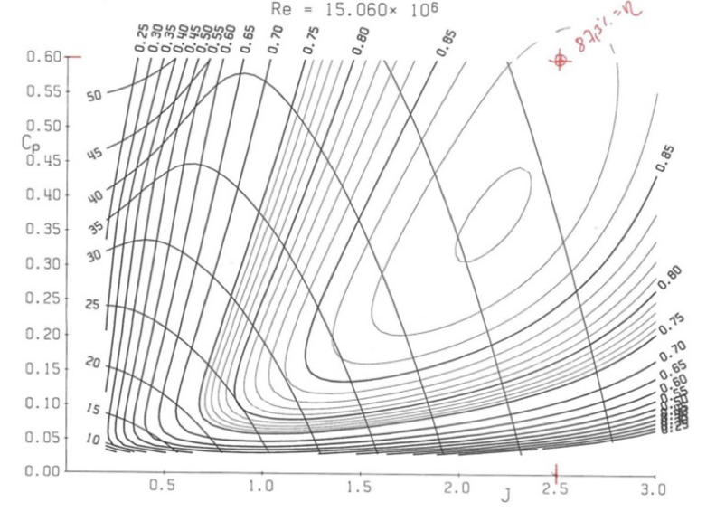 The ideal design solution would be the slowest turning propeller with the biggest diameter possible while staying below a maximum blade tip Mach number of 0.88 at high speed. A good example of this configuration is the P51 Mustang from World War II, one of the fastest propeller fighters ever built.
Of course, the maximum allowable propeller diameter is limited by the airframe designer. Therefore, to achieve the highest efficiency possible only the propeller RPM, diameter and the number of blades can be varied.
A change in RPM results in a change in pitch, thanks to the propeller governor. However, propeller RPM is not only a factor in propeller efficiency but also in other airplane performance related characteristics. Such factors include airplane speed and cruise fuel efficiency, endurance and specific range capability, noise and vibration. These airplane level factors are also important as they relate to propeller design and RPM.
Reducing the diameter of the propeller, not only lowers the level of noise produced, it also reduces compressibility losses, increasing the propeller efficiency. Without the addition of more blades, the older classic propellers would be aerodynamically overloaded resulting in partial stall and lower overall efficiency.
As engine power is increased, the propeller needs to transmit this power to the air flow passing through the propeller disk to generating thrust. A parameter used to evaluate this relationship is the Solidity Ratio, a ratio of propeller blade area to overall propeller disk area, defined as:
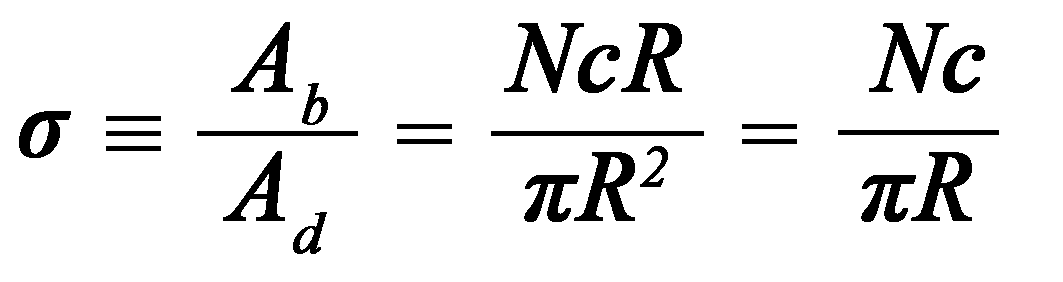 where N is the number of blades, c is the chord of the blade and R is the diameter of the propeller disk.
The more power available from the engine, the higher the required solidity ratio to absorb that power. Increasing the chord of the blades is an option, however, this leads to increased interference between the blades reducing the propeller efficiency as well as higher blade pitch change forces and lower blade frequencies increasing the risk of a resonance. Therefore, the addition of blades to the propeller system is the best approach to increasing the solidity ratio.
Propeller systems with additional blades improve propeller efficiency, converting engine power to thrust, and the lift distribution along the blades, making take-off, climb (single- and multi-engine) and cruise performance comparable to larger diameter or fewer blade propeller systems. This propeller combination of more blades with a smaller diameter, results in a reduction in airframe noise results as the blade tips are quieter at the lower Mach number and at a greater distance to the fuselage, making the flight even more comfortable and reducing fatigue in the flight crew and passengers. The additional benefit of having a smaller propeller diameter is the additional ground clearance to mitigate FOD damage to the blades, which is critical if operating on unimproved runways.
Propeller design is not only governed by aerodynamics but also the structural requirements. The lower weights of newer blade materials reduce the loads not only on the blade itself, but also on the propeller hub and related blade retention hardware. By designing the lightest blades with the best vibration dampening qualities, the structural requirements of the hub and retention hardware can be more easily addressed.
The trend from metal, to structural composite, and finally natural composite blade construction shows the clear vibration and damping characteristic improvements gained with each respective technological advancement. The following figure shows the vibration and damping characteristics associated with various blade designs.
 With respect to durability, all major propeller manufacturers have certified the use of composite blades to the latest 14 CFR Part 35 requirements, or the equivalent CS-P certification requirements, to take advantage of their benefits. Bird strike testing is a major activity in the certification of these blades. The testing involves firing hundreds of birds at the blades in a series of tests, under strict conditions defined by the certification authority, to demonstrate survivability of such impacts.
The following pictures show an in-service incident where an 8-pound stork impacted a turboprop airplane during takeoff. The pictures below show the damage to the propeller blade (left) and to the wing leading edge (right).

In addition to the bird strike requirements for the certification of composite blades, lighting strike can be a major challenge in the certification process. All composite blades must meet lightning strike requirements, with the ideal design practice being that the load carrying structure is not conductive. In the situation where the load carrying structure is conductive, a lightning strike would necessitate scrapping of the blade. In the case where a natural composite is used as the load bearing structure, after lightning strike, the blade can be repaired, in many cases with a field-repair and/or overhauled.
The following picture provides an example of a lightning strike on a natural composite blade. The picture on the left shows where the lighting strike hit the blade, and the picture on the right where the lighting left the blade.

In addition to lower weights and the corresponding structural and vibration advantages, composite blades have the advantage of longevity. Unlike metal propeller blades, composite blades are resistant to corrosion. Additionally, composite blades are easier to maintain and repair. Unlike composite propellers, the performance of metal propellers begins to deteriorate from the day they are installed as a result of the grinding away of surface blemishes, gouges and other FOD damage, permanently removing material during overhaul and repair. During their limited service life, metal blades surfaces deviate further and further from their designed outer mold line (OML) until ultimately they must be replaced. On the other hand, composite blades are repaired by removing damage, then adding material back onto the blade, thereby restoring its OML. In this way, many composite blades have unlimited life and use. The oldest composite blades have now been in-service for 80 years and are still airworthy.
Improvements in design methodology, analysis tools and new materials technologies have allowed propeller designers to push their designs closer and closer toward the maximum possible efficiencies by adding more propeller blades, going beyond what was possible with the limitations of classic designs and materials. The by-products of these efficiencies, in the form of lower noise, lower vibration and improved durability and longevity clearly align with the desire of operators to lower operating costs and improve the overall experience for their crew and passengers. Higher blade counts are propelling the industry into the future.
The company website for MT Propellers is www.mt-propeller.com. MT Propeller is the manufacturer of BLR's Whisper Prop® propellers. BLR generously donated a set of the BLR Whisper Props® for attendees to bid on at the KingAir Gathering 2023 auction.